HowTo: change service UUIDs using BlendMicro

HowTo: change service UUIDs using BlendMicro

For the Body Sensor project, I needed to change the default service UUID that a BlendMicro board was advertising. If you are here, it probably means you also want to get this done. I hope you will find this tutorial useful.

The Bluetooth Low Energy(BLE) connection will be established between an Intel Edison board  (central device) and a BlendMicro peripheral. 

  1. First things first! Install the required software:

    On the BlendMicro side you will need :

               Install the Arduino IDE.

               Extract your downloads and copy the Hardware folder from the Add-On package in                    your Arduino folder.

               Copy the BLE folder from the nRF8001 SDK in the Libraries folder.

               Do the same for the nRF8001 Library.

               In the end your folders should look like this:

               hw

                libs

           For programming the Intel Edison I am using:

            Make sure you have Bluetooth working on your Edison. You may find the new Bluetooth Guide from Intel useful.

     2. Edison code

         Now that we have all the tools, we can proceed with writing the code for the Edison.Our aim is to discover the BlendMicro and to printout the advertising service UUID.  


var noble = require('noble');
var devices = new Array();

noble.startScanning();
console.log('Try to find BLE devices...');

noble.on('discover', function (peripheral) {
    peripheral.connect(function (error) {
        if (error) {
            console.log(error);
        } else {
            devices.push(peripheral);
        }
    });
    console.log(peripheral.advertisement.localName);
    console.log(peripheral.address);

});

setTimeout(function () {
    console.log("Stop discovery \n");
    noble.stopScanning();
    reportDevices(devices);
}, 10000);

var reportDevices = function (listOfDevices) {
    for (var idx in listOfDevices) {
        console.log(' ' + idx + ' uuid: ' + listOfDevices[idx].advertisement.localName);
        console.log("\tLE: " + listOfDevices[idx]);
        console.log('\tConnected to peripheral: ' + listOfDevices[idx].uuid);
                }
}   
 

         Next, we load the "SimpleChat" example from the RBL_nRF8001 library on the BlendMicro.

         simplechat

         When running the code on the Edison, we can see that by default the BlendMicro advertises service 180b.

UUID1

     3. Using nRFgo Studio

  • Load your RBL_nRF8001.xml file (under C:\Users\uc-office\Documents\Arduino\libraries\RBL_nRF8001) into the nRFgo. 

      nrfgo1 

         Check what service is being advertised. You will find this information in the GAP Settings tab, under Service Solicitation and Local Services.

        nrfgo3          

    • Change UUID base from 180b to 180a,  click OK and go to File -> Save

           nrfgo4

                                     Now your .xml file is updated.

    • Generate the files used by RBL_nRF8001 library. Select the same destination folder where RBL_nRF8001.xml file is found.

             nRfgo6

         The following files will be generated:

            nrfgogenerated


    • Rename services.h to RBL_services.h and save the old one under a different name

            nrfgorename2

    • Upload the SimpleChat example again and when finished, RESET the BlendMicro board (!!! Don’t forget this step)

          Now the service UUID should be updated to 180a:

UUID2

           Thanks for reading!

Continue reading
Rate this blog entry:
1
21038 Hits 0 Comments

Autonomous Prototype Model Car

Autonomous Prototype Model Car

(*) Blog image taken from http://www.carpages.co.uk/audi/audi-r8-14-12-07.asp

Researcher for project : Afshin KHALGHDOOST 

Study degree : BSc from school of engineering Polytechnique Paris-UPMC; Current student for Master degree in this school

Today, we can observe that we are surrounded by machines and each of them is destined to assure a need of our society. Each of them exists in different sizes from an airplane to a mobile phone. We have always understood that these machines have been created by passing a complicated engineering process. It is true that sometimes many of them are manufactured by validating a long chain of reflection, high technology conception, design, tests and etc. This concerns particularly cars which became an essential element for our society and a part of our life depends on these machines. As regards cars uses, they enable people to move from a point to another point and they also provide several advantages such as saving money, energy, time.
Meanwhile, as the technology has been improved over the time, these machines have been equipped with advanced sensors, Global Positioning System (GPS), motors and electronic components for a better control and comfort for driver and its passengers. Many industrial project are currently running for this kind of new generation machine like for example Google project named “Google Self-Driving Car “ which consist of using cameras , radars , GPS receiver and sensors for an auto control. Other companies have also launched similar projects for example Mercedes, Jaguar and etc. It has always been an opened question to ask if these machines are technically very complicated to be modeled in small size like a toy or not? To answer this question, our laboratory is engaged to create an electronic Autonomous Prototype Model Car (APMC) which can be not only controlled by a regular game controller but also drive on autonomous way and can reach the destination by avoiding obstacles.

In this project, we will work on this electronic car which can be controlled in different ways. There are 2 important ways of communication for the APMC.

The first way is based on Bluetooth communication between the APMC and a game controller. This type of communication concerns short range activity. Control orders come from the controller wirelessly and the APMC detect immediately orders and behave exactly as it is asked by user.

The second way of communication is based on Global System for Mobile Communications (GSM). This type of communication will be used for long range control. User controls by distance that APMC. Orders arrive via GSM from user to the APMC and after machine will interpreter the information and execute the order.

How must APMC work?

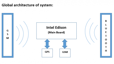
There is a main board in this APMC which is considered as the heart of the project. This card constitute an important point to manage data. It allows the APMC to move by controlling directly direction and speed of wheels. This is the storage center of information. It checks instantaneously the position of the car and can after provides these information to other devices which are located in ray of recognition and are connected to the APMC. As it was explained above, there are two forms of communication for this APMC. The first way based on Bluetooth functionalities, receiving information coming from game controller. User is the person who choses the next near position of the car by moving simply the multidirectional buttons. He can also control the speed via different touches.
These information are transited via Bluetooth and are translated according to a protocol in the main board. After the interpretation of data, an order will be sent to the concerned component. This type of communication is in one-direction because information arrive only from game controller and there is not any information in return. In the second way of communication, user sends via GSM coordinates of a position to the APMC. Once the information is received by the main board, it calculates new routes and only the shortest path to the destination. After it starts its route and communicate its current coordinates position via GSM to the user. Information is transited in both directions.

Constraints on automatic function

The APMC must be able to reach the destination by avoiding any obstacles on its route. For this goal, sensors will be installed on the APMC. Use of digital sensors may prevent the main board from using the CAN component. Other factors such as wind, rain and … should be take into account for functional work of this APMC. It must continue its route and any external factor cannot cause the overthrow of that. If a problem occurs during operation phase of the APMC, a warning message will be sent to user giving the current position with an emergency status.

b2ap3_thumbnail_Sans-titre.png

Which technologies for this project?

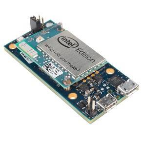
For the main board: Intel Edison with kit for Arduino (Bluetooth integrated)

b2ap3_thumbnail_ba.jpg

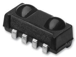
Digital sensors :
Undefined  (possible : VISHAY  TSOP75236TT  IR SENSOR IC 36KHZ) –> FARNELL.COM

b2ap3_thumbnail_ba2.jpg


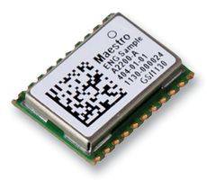
GPS module :
Undefined (possible : MAESTRO WIRELESS SOLUTIONS  A2200A  GPS MODULE, ROM BASED, MINI OUTLINE ) -> FARNELLE.COM

b2ap3_thumbnail_ba3.jpg

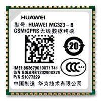
GSM module:
Undefined  (possible : HUAWEI  MG323-B  GSM MODEM, HUAWEI QUADBAND, LCC) -> FARNELL.COM

b2ap3_thumbnail_ba4.jpg


Objectives
  1. STEP 1
    ☒Preparation and understanding of INTEL EDISON
    ☒Connect game controller to the Main Board via Bluetooth
    ☐Handling motors and controlling speed and direction of wheels by game controller
    ☐Preparation of algorithms, protocols and assembly phase
    ☐Test and verification phase
  2. Step 2
    ☐2.1 Preparation and understanding of the concept
    ☐Connect GPS and GSM to the Main Board
    ☐Handling motors and controlling speed and direction of wheels by game controller
    ☐Preparation of algorithms, protocols and assembly phase
    ☐Test and verification phase

Deadlines

1.1 [ from 1 June to 7 June ]

1.2 [ from 7 June to 14 June ]

1.3 [ from 14 June to 21 June ]

1.4 [ from 21 June to 25 June ]

1.5 [ from 25 June to 30 June ]

2.1 [ from 1 July to 4 July ]

2.2 [ from 4 July to 6 July ]

2.3 [ from 6 July to 10 July ]

2.4 [ from 10 July to 20 July ]

2.5 [ from 20 July to 28 July ] 

---------------------------------------------------------------------------------------------------------------------------------------


Continue reading
Rate this blog entry:
1
16772 Hits 0 Comments