Autonomous Prototype Model Car

(*) Blog image taken from http://www.carpages.co.uk/audi/audi-r8-14-12-07.asp

Researcher for project : Afshin KHALGHDOOST 

Study degree : BSc from school of engineering Polytechnique Paris-UPMC; Current student for Master degree in this school

Today, we can observe that we are surrounded by machines and each of them is destined to assure a need of our society. Each of them exists in different sizes from an airplane to a mobile phone. We have always understood that these machines have been created by passing a complicated engineering process. It is true that sometimes many of them are manufactured by validating a long chain of reflection, high technology conception, design, tests and etc. This concerns particularly cars which became an essential element for our society and a part of our life depends on these machines. As regards cars uses, they enable people to move from a point to another point and they also provide several advantages such as saving money, energy, time.
Meanwhile, as the technology has been improved over the time, these machines have been equipped with advanced sensors, Global Positioning System (GPS), motors and electronic components for a better control and comfort for driver and its passengers. Many industrial project are currently running for this kind of new generation machine like for example Google project named “Google Self-Driving Car “ which consist of using cameras , radars , GPS receiver and sensors for an auto control. Other companies have also launched similar projects for example Mercedes, Jaguar and etc. It has always been an opened question to ask if these machines are technically very complicated to be modeled in small size like a toy or not? To answer this question, our laboratory is engaged to create an electronic Autonomous Prototype Model Car (APMC) which can be not only controlled by a regular game controller but also drive on autonomous way and can reach the destination by avoiding obstacles.

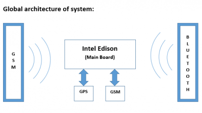
In this project, we will work on this electronic car which can be controlled in different ways. There are 2 important ways of communication for the APMC.

The first way is based on Bluetooth communication between the APMC and a game controller. This type of communication concerns short range activity. Control orders come from the controller wirelessly and the APMC detect immediately orders and behave exactly as it is asked by user.

The second way of communication is based on Global System for Mobile Communications (GSM). This type of communication will be used for long range control. User controls by distance that APMC. Orders arrive via GSM from user to the APMC and after machine will interpreter the information and execute the order.

How must APMC work?

There is a main board in this APMC which is considered as the heart of the project. This card constitute an important point to manage data. It allows the APMC to move by controlling directly direction and speed of wheels. This is the storage center of information. It checks instantaneously the position of the car and can after provides these information to other devices which are located in ray of recognition and are connected to the APMC. As it was explained above, there are two forms of communication for this APMC. The first way based on Bluetooth functionalities, receiving information coming from game controller. User is the person who choses the next near position of the car by moving simply the multidirectional buttons. He can also control the speed via different touches.
These information are transited via Bluetooth and are translated according to a protocol in the main board. After the interpretation of data, an order will be sent to the concerned component. This type of communication is in one-direction because information arrive only from game controller and there is not any information in return. In the second way of communication, user sends via GSM coordinates of a position to the APMC. Once the information is received by the main board, it calculates new routes and only the shortest path to the destination. After it starts its route and communicate its current coordinates position via GSM to the user. Information is transited in both directions.

Constraints on automatic function

The APMC must be able to reach the destination by avoiding any obstacles on its route. For this goal, sensors will be installed on the APMC. Use of digital sensors may prevent the main board from using the CAN component. Other factors such as wind, rain and … should be take into account for functional work of this APMC. It must continue its route and any external factor cannot cause the overthrow of that. If a problem occurs during operation phase of the APMC, a warning message will be sent to user giving the current position with an emergency status.
b2ap3_thumbnail_Sans-titre.png

Which technologies for this project?

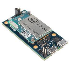
For the main board: Intel Edison with kit for Arduino (Bluetooth integrated)
b2ap3_thumbnail_ba.jpg

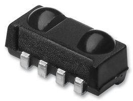
Digital sensors :
Undefined  (possible : VISHAY  TSOP75236TT  IR SENSOR IC 36KHZ) –> FARNELL.COM
b2ap3_thumbnail_ba2.jpg


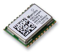
GPS module :
Undefined (possible : MAESTRO WIRELESS SOLUTIONS  A2200A  GPS MODULE, ROM BASED, MINI OUTLINE ) -> FARNELLE.COM
b2ap3_thumbnail_ba3.jpg

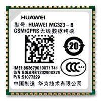
GSM module:
Undefined  (possible : HUAWEI  MG323-B  GSM MODEM, HUAWEI QUADBAND, LCC) -> FARNELL.COM
b2ap3_thumbnail_ba4.jpg


Objectives
  1. STEP 1
    ☒Preparation and understanding of INTEL EDISON
    ☒Connect game controller to the Main Board via Bluetooth
    ☐Handling motors and controlling speed and direction of wheels by game controller
    ☐Preparation of algorithms, protocols and assembly phase
    ☐Test and verification phase
  2. Step 2
    ☐2.1 Preparation and understanding of the concept
    ☐Connect GPS and GSM to the Main Board
    ☐Handling motors and controlling speed and direction of wheels by game controller
    ☐Preparation of algorithms, protocols and assembly phase
    ☐Test and verification phase

Deadlines

1.1 [ from 1 June to 7 June ]

1.2 [ from 7 June to 14 June ]

1.3 [ from 14 June to 21 June ]

1.4 [ from 21 June to 25 June ]

1.5 [ from 25 June to 30 June ]

2.1 [ from 1 July to 4 July ]

2.2 [ from 4 July to 6 July ]

2.3 [ from 6 July to 10 July ]

2.4 [ from 10 July to 20 July ]

2.5 [ from 20 July to 28 July ] 

---------------------------------------------------------------------------------------------------------------------------------------


Continue reading
Rate this blog entry:
1
16772 Hits 0 Comments

First part of project : Manual control

The first part of project is terminated and now it is time to explain more about the conception of this system. At the begining I must remind you that this project has been programmed completely using node.js tools which enable programmers to make application related to web and networking. It can be also used for local application for real time data transfers using Wi-Fi , Bluetooth , RF modules and differents sensors but the main purpos remains for web activities. As the format of node.js shows , applications are written in Javascript language which can be understood by the common human. It is much easier and more robust than Java and also from diffrenet languages. Node.js applicatipon can be developped and run in different environnement such as Linux , Microsoft Windows

Different technologies for the first part of the project :

Intel Edison Kit forArduino

b2ap3_thumbnail_photo-2.JPG


It is clear that this programming card is too much complicated for this part of project which consist of control the APMC via game controller using a Bluetooth Connection. But I should say that this card will be useful later for GPS and GSM modules connections and also for diffrerent sensors which will be installed directly on this machine.Other adventage of this card is its flexibility , in fact it offers several important adavantages: It has a preinstalled Bluetooth model based on BLE technology with a lower consumption.It includes also PWM ports which give this possibility to control motors of the APMC.Intel Edison Board is equiped of analog and digital pins which have capacity to be set as input or output. It can be programmed easily by using different softwares like for example Arduino or Intel Iot XDK Edition.I must notice that in this project we programmed this card by entering directly into the kernel of this board. I have not used neither the arduino software for programing nor the usual codes for Bluetooth device detection.

It must be said that for security reasons , codes to handle Bluetooth connection do not work properly. In fact the board is unable to find the serial port channel of Bluetooth and that's why the connection is refused each time. This code is shown below:

var btSerial = new (require('bluetooth-serial-port')).BluetoothSerialPort();
 
btSerial.on('found', function(address, name) {
    btSerial.findSerialPortChannel(address, function(channel) {
        btSerial.connect(address, channel, function() {
            console.log('connected');
 
            btSerial.write(new Buffer('my data', 'utf-8'), function(err, bytesWritten) {
                if (err) console.log(err);
            });
 
            btSerial.on('data', function(buffer) {
                console.log(buffer.toString('utf-8'));
            });
        }, function () {
            console.log('cannot connect');
        });
 
        // close the connection when you're ready 
        btSerial.close();
    }, function() {
        console.log('found nothing');
    });
});
 
btSerial.inquire();

This code which is written in Javascript has been provided by NPM archive package named bluetooth-serial-port from author 'eelco'. Unfortunatly this code for reasons mentionned up can not work.
Consequently , I decided to chose another strategy which consist of accesing the kernel file that is created automatically when a bluetooth device is paired and connected. My goal was to receive instantly all incoming data from Bluetooth module and after be able to analyze it and decide for motor controlling and etc, according to a protocole.
In order to achieve this goal , I decided to create my own library using EVTEST tool which is included in Intel Edison documentation. EVTEST tool is a programme written in C language giving possibility to receive not only all incoming data from Bluetooth but also from any different type of devices. In case you want to use this application , you must have at least GCC compiler to generate binary files.  All files of this programm are open source and are available at next hyper link : http://cgit.freedesktop.org/evtest/ .
After analyzing source code in C language , I tried to adapt these codes to CPP language format in order to make them compilable by G++ compiler. Then I created a full package NPM library enabling to receive all of incoming data from different devices. These libraries are availabe in next link and can be used as shown in this example.

Below , can be seen the code that I used to control the behaviour of the APMC according to orders arrived from the controller :

/* Copy-Right 2016 - Author : Afshin KHALGHDOOST */

/* definition of objects and call for libraries */
var addon = require('./build/Release/addon');
var obj = new addon.DS4("/dev/input/event2");

/* call for cylon */
// Cylon is the name of library which enable you to control motors , wheels and so on.
// for more information , please visit http://cylonjs.com
var Cylon = require('cylon');

Cylon.robot({ connections: { edison: { adaptor: 'intel-iot'} // definition of device in order to use different fucntionalities }, devices: { // definition of differents parameters for different motor control // In this example there are 4 parameters //motor_rear1: to control backward movement //motor_rear2: to control forward movement //motor_front1: to control left direction //motor_front2: to control right direction motor_rear1: { driver: 'motor', pin: 3, connection: 'edison' }, motor_rear2: { driver: 'motor', pin: 6, connection: 'edison' }, motor_front1: { driver: 'motor', pin: 5 ,connection: 'edison' }, motor_front2: { driver: 'motor', pin: 9 ,connection: 'edison' } }, work: function(my) { // function to define right movement function right(){ my.motor_front1.speed(250); my.motor_front2.speed(0); } // function to define left movement function left(){ my.motor_front1.speed(0); my.motor_front2.speed(250); } // function to define mddle position for wheels function middle_position(){ my.motor_front1.speed(250); my.motor_front2.speed(250); } // Initialization fo wheels movement // blocking all motors function init(){ my.motor_rear1.speed(250); my.motor_rear2.speed(250); my.motor_front1.speed(250); my.motor_front2.speed(250); } init(); while(true){ // show_flows is a function of our library which can search permanently for Bluetooth devices // when a connection with Bluetooth device is established , data are immedialtely analyzed obj.show_flows(); // Rz means when user move the right stick of game controller // for these next 3 if conditions , thse speed is linear to the movement // the more user moves the right stick , the more speed increases if (obj.value()<160 && obj.value()>90 && obj.identifier() == 'Rz'){ my.motor_rear1.speed(250); my.motor_rear2.speed(250); } if (obj.value()<90 && obj.identifier() == 'Rz'){ my.motor_rear1.speed(250); my.motor_rear2.speed(obj.value()); } if (obj.value()>160 && obj.identifier() == 'Rz'){ my.motor_rear2.speed(250); if ( obj.value() < 250) my.motor_rear1.speed(250-obj.value()); } // Hat0X means right or left directional buttons on PS4 games controlelr if (obj.value()==1 && obj.identifier() == 'Hat0X') left(); if (obj.value()==-1 && obj.identifier() == 'Hat0X') right(); if (obj.value()==0 && obj.identifier() == 'Hat0X') middle_position(); if (obj.value()==0 && obj.identifier() == 'Hat0X') middle_position(); } } }).start();

 Here is general algorithm shceme for a better understanding of this code :

 rsz screenshot from 2015 07 08 162036

In order to use these libraries , they must be included via Intel IoT XDK Edition software where the main code must be written in main.js file . Package.json must also be precised during upload and build process.
All files are available for downloading at the bottom ot this article.


Game Controller :
For the controller I decied to use a normal game controller available on market. I chosed a PlayStation 4 controller. I insist on the fact that any kind of game controller can be used but in this case I settled for a PS4 game controller.

b2ap3_thumbnail_photo-4.JPG

rsz screenshot from 2015 07 08 165939

These information are provided by http://www.ps4playstation4.com


Motor drive :
The motor drive that has been used is named (L9110) Dual Channel Motor Driver Module. This motro device enable us to control maximum 2 motors. The first one , I used for wheels acceleration and the other for wheels direction. The power is about 12 V and energy pins are connected directly to the batteries.
One of the specificities of this motor device is that there are 4 outputs. For each motor , 2 outputs are dedicated. You have to connect the VCC and GND to these 2 pins. By permuting VCC and GND , you only change the direction of wheels.

rsz screenshot from 2015 07 08 165945

Essential tutorial:
Now the question is to ask how we can execute automatically this programm at system start up ?
Well, to answer this question , we must know the opertaion of Intel Edison. It must be noticed at system start up of this board which has a Linux as operating system , every essentiel software and hardware functionalities are initialized and then set to stand by. Each of this functionality has a file in the kernel and exactly in /lib/systemd/system
You must know that if you want your programm be launched automaticaly at start up , you have to create a kernel file in that path mentionned above.But before starting, you should be aware that the work of your programm depends on activation of Bluetooth functionality. With Intel Edison , the default settings is configured to disable automatically Bluetooth functionality for each reboot. So in this small tutorial we begin by creating a Bluetoth kernel file to launch automatically Bluetooth functionality by avoiding to ente rrfkill unblock bluetooth command manually.
To create this kernel file you have to follow next easy steps :

1) You open gedit or other text editor and you put next code inside:

 [Unit]
 Description=BTLAUNCHER
 After=bluetooth.target
 Before=systemd-user-sessions.service
 [Service]
 Type=simple
 RemainAfterExit=true
 ExecStart=/usr/sbin/rfkill unblock bluetooth
 Environment="HOME=/home/root"
 WorkingDirectory=/home/root/
 [Install]
 WantedBy=multi-user.target


2) You save this code as BTLAUNCHER.service
Don't forget that .service format is reserved to be used by system.

3) You put this file into /lib/systemd/system/ . Be aware that you have to change rights. To avoid all problems I used next line command :

chmod 777  BTLAUNCHER.service


4) You must activate the file that you have just created :

systemctl enable /lib/systemd/system/BTLAUNCHER.service


and then

systemctl start BTLAUNCHER.service


** You can monitor this kernel file activity by using next line command:

 journalctl -f -u BTLAUNCHER.service


5) Reboot

After creating Bluetooth kernel file , you can now create another kernel file to launch automatically this programm by following previous steps and change only the setp 1 code. Use next code :

[Unit]
Description=MyProg
After=bluetooth.service
Requires=bluetooth-rfkill-event.service
Requires=blink-led.service 
[Service]
TimeoutStartSec=0
Type=simple
RemainAfterExit=true
ExecStart=/usr/bin/node /home/root/.node_app_slot/main.js
[Install]
WantedBy=multi-user.target

 
dont't forget that on line 10 , you have to specify the path where node is installed followed by the path where you main.js file and all other files are gathered and uploaded inside your Intel Ediso card.
Please note that you have to change the .service file name and follow exactly steps which are mentionned above.


Continue reading
Rate this blog entry:
0
4926 Hits 0 Comments